Ein kapazitiver offener Draht soll auf einem Arduino Uno Pin die LED 13 ein- und ausschalten.
Die verwendete Hardware:
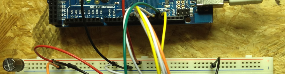
– Arduino Uno
– 1nF Kondensator
– Draht
Hier wird der Pin8 verwendet, es ist aber auch jeder andere digitale ( und analoge ) PIN möglich. In Reihe wird ein 1nF Kondensator gelegt, das sorgt für eine Gleichspannungsentkopplung und schützt den Arduino Pin vor Überspannungen.
Die Funktion gibt für das offene Ende einen typischen Wert von 2 aus.
Wenn man nun das offene Ende anfasst, gibt die Funktion einen Wert 4 bis 17 raus, je nachdem wie gut man geerdet ist. Deshalb habe ich die Schaltschwelle auf 4 gelegt.
Die LED 13 wird mit diesem Programm eingeschaltet solange das offene Ende angefasst wird.
Das fertige Programm.
// LED 13 einschalten mit einem kapazitiven Schalter
// Die LED ist an solange der Draht berührt wird
// PIN 8 > 1nF > offenens Ende
//
// von Matthias Busse 4.12.2014 Version 1.0

int touch;

void setup() {
  Serial.begin(4800);
  pinMode(13, OUTPUT);
}

void loop() {
  touch=readCapacitivePin(8);
  Serial.println(touch);
  if(touch < 4)
    digitalWrite(13, LOW);
  else
    digitalWrite(13, HIGH);
  delay(100);
}

// readCapacitivePin
//  Input: Arduino pin number
//  Output: A number, from 0 to 17 expressing
//  how much capacitance is on the pin
//  When you touch the pin, or whatever you have
//  attached to it, the number will get higher
uint8_t readCapacitivePin(int pinToMeasure) {
  // Variables used to translate from Arduino to AVR pin naming
  volatile uint8_t* port;
  volatile uint8_t* ddr;
  volatile uint8_t* pin;
  // Here we translate the input pin number from
  //  Arduino pin number to the AVR PORT, PIN, DDR,
  //  and which bit of those registers we care about.
  byte bitmask;
  port = portOutputRegister(digitalPinToPort(pinToMeasure));
  ddr = portModeRegister(digitalPinToPort(pinToMeasure));
  bitmask = digitalPinToBitMask(pinToMeasure);
  pin = portInputRegister(digitalPinToPort(pinToMeasure));
  // Discharge the pin first by setting it low and output
  *port &= ~(bitmask);
  *ddr  |= bitmask;
  delay(1);
  uint8_t SREG_old = SREG; //back up the AVR Status Register
  // Prevent the timer IRQ from disturbing our measurement
  noInterrupts();
  // Make the pin an input with the internal pull-up on
  *ddr &= ~(bitmask);
  *port |= bitmask;

  // Now see how long the pin to get pulled up. This manual unrolling of the loop
  // decreases the number of hardware cycles between each read of the pin,
  // thus increasing sensitivity.
  uint8_t cycles = 17;
       if (*pin & bitmask) { cycles =  0;}
  else if (*pin & bitmask) { cycles =  1;}
  else if (*pin & bitmask) { cycles =  2;}
  else if (*pin & bitmask) { cycles =  3;}
  else if (*pin & bitmask) { cycles =  4;}
  else if (*pin & bitmask) { cycles =  5;}
  else if (*pin & bitmask) { cycles =  6;}
  else if (*pin & bitmask) { cycles =  7;}
  else if (*pin & bitmask) { cycles =  8;}
  else if (*pin & bitmask) { cycles =  9;}
  else if (*pin & bitmask) { cycles = 10;}
  else if (*pin & bitmask) { cycles = 11;}
  else if (*pin & bitmask) { cycles = 12;}
  else if (*pin & bitmask) { cycles = 13;}
  else if (*pin & bitmask) { cycles = 14;}
  else if (*pin & bitmask) { cycles = 15;}
  else if (*pin & bitmask) { cycles = 16;}

  // End of timing-critical section; turn interrupts back on if they were on before, or leave them off if they were off before
  SREG = SREG_old;

  // Discharge the pin again by setting it low and output
  //  It's important to leave the pins low if you want to
  //  be able to touch more than 1 sensor at a time - if
  //  the sensor is left pulled high, when you touch
  //  two sensors, your body will transfer the charge between
  //  sensors.
  *port &= ~(bitmask);
  *ddr  |= bitmask;

  return cycles;
}
Hier gibt es die fertige Routine mit Erklärung.
Zum Teil 2 mit Umschalter und Teil 3 mit Dimmer.
von Matthias Busse
Pingback: Kapazitiver LED Umschalter mit einem einfachen, offenen Draht | Shelvin – Elektronik ausprobiert und erläutert
Pingback: Eine LED mit einem kapazitiven Schalter dimmen oder umschalten | Shelvin – Elektronik ausprobiert und erläutert
Hi
Sehr interessant. Ich möchte das Ganze an einem Raspberry machen.
Ich steh aber beim Eingangspin auf dem Schlauch.
Ist den der Eingang des AVR analog oder digital (hat der Atmega einen A/D-Wandler integriert)?
Bei digitalem Eingang verstehe ich nicht, wie Werte von 2 bis n ausgelesen werden können.
Müsste ich dann am RPI noch einen MPC3008 A/D-Wandler anschliessen?